Draw Hinges on a Circle Creo
Geometry Updates
COMSOL Multiphysics® version five.5 brings extensive improvements to geometry modeling with new sketching tools. On top of this, there are several updates to the general functionality, including new transform operations, and new parts in the Office Libraries. Read more than well-nigh these updates below.
New Sketching Tools
A set of new sketching tools for planar drawings are available when working with 2D geometry models and 3D work planes. On the new Sketch toolbar there are options for drawing polygons, circular arcs, interpolation curves, Bezier curves, rectangles, squares, circles, and ellipses. These drawing options are completely new versions of the respective functionality bachelor in earlier versions of COMSOL Multiphysics®.
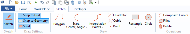 The new Sketch tab with various tools for creating planar drawings.
A new polygon tool lets you lot move points and lines interactively by clicking and dragging. When editing point coordinates, the respective signal is highlighted with a ruddy circle in the Graphics window. Similarly, a new tool for creating an interpolation curve allows you to interactively draw the curve. To edit the bend, y'all can either drag a betoken in the Graphics window or alter the bespeak coordinate in a table. While dragging a point, a green guideline indicates alignment with other points, bachelor for several of the new sketching tools.
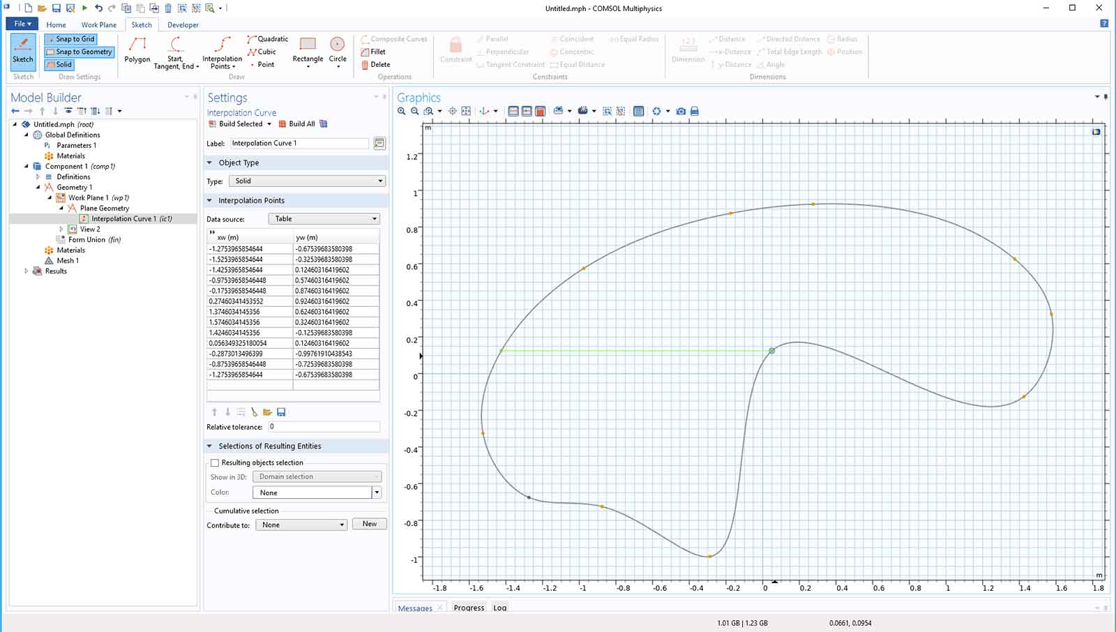 The new interactive interpolation bend tool with a green guideline indicating alignment between points.
The tools for cartoon squares, rectangles, circles, and ellipses have new options for interactive editing. Auxiliary points and lines are associated with the geometry primitives, including circular arcs, that assist in interactively irresolute the object'southward parameters past clicking and dragging. For example, when using the mouse to elevate an entity, you can press Ctrl and/or Shift to change how the other entities move. In a similar way, the new tools for creating Bezier curves tin be drawn and edited interactively. The snapping functionality has been improved and extended to include snapping to existing lines and circles equally well equally the possibility of snapping lines and circles that you draw to existing points, lines, and circles. Additionally, when y'all have multiple features in the sketch, yous can double-click on a highlighted vertex or border to open the corresponding Settings window for that feature.
Three new options for creating round arcs are available for various input combinations: Start, Center, Bending, Start, Tangent, End, and Start Middle, End. A new Sketch Fillet operation lets you interactively elevate a fillet starting from a corner. The fillet radius will exist adamant past the mouse release point and can be subsequently edited.
If you take a license for the Design Module, the Sketch tab also contains buttons for using geometric constraints and dimensions. See the Pattern Module release highlights page for more information.
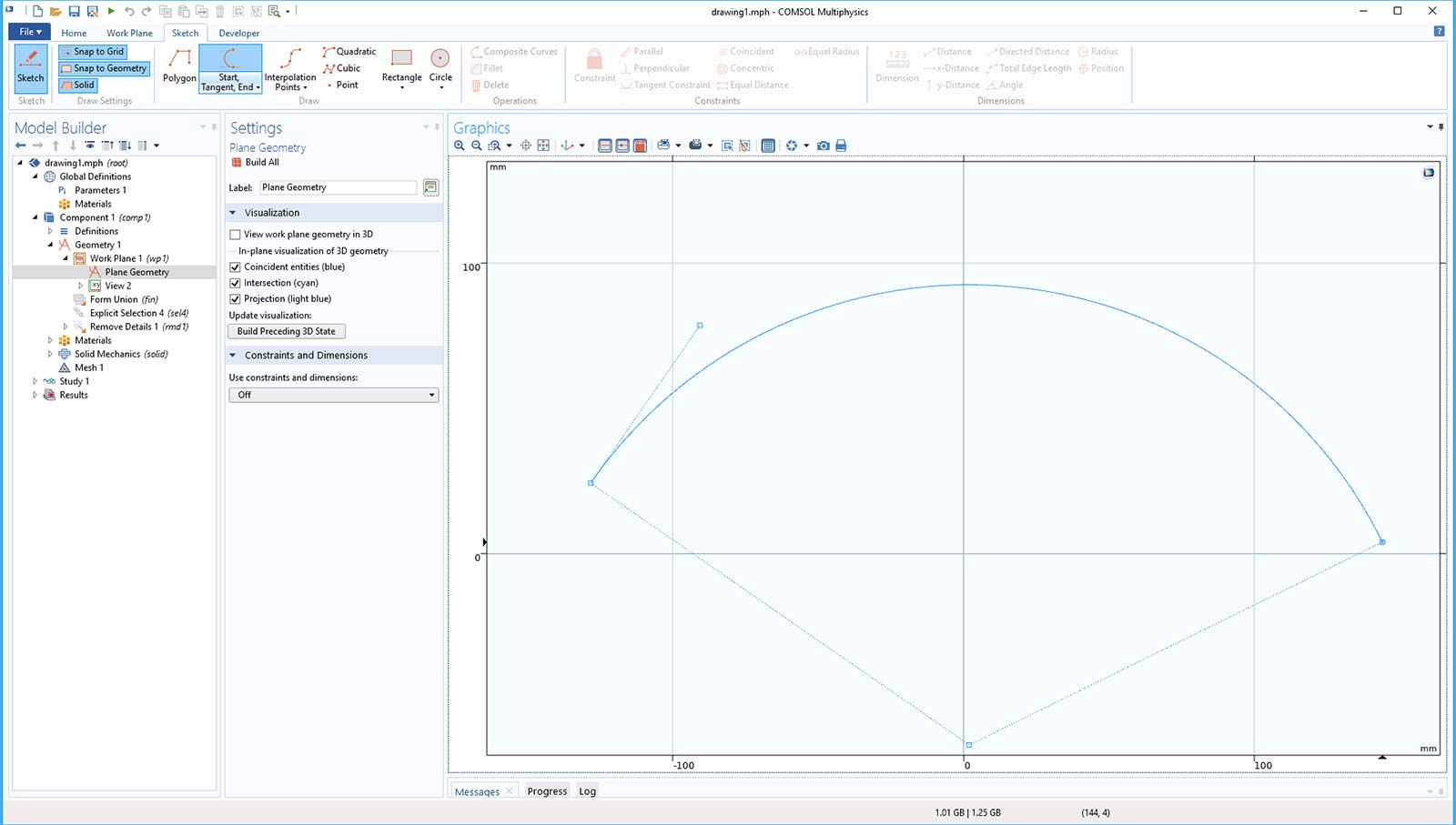 A round arc defined with the new option for specifying first signal, tangent, and end indicate.
New Rotate, Move, and Copy Options
There are now more than ways to rotate 3D geometry objects with the Rotate feature: yous can choose to specify an axis and rotation or to specify Euler angles. This selection is likewise bachelor in Piece of work Plane features divers using the Transformed plane blazon and in the Part Instance nodes in the Position and Orientation of Output department. The Move and Re-create features at present include a Specify list in the Deportation section with the options Displacement vector and Positions. This makes it possible to specify the motion using a vertex or coordinates for the old position and vertices or coordinates for the location to move and copy to.
New Rigid Transform Performance
A new feature, Rigid Transform, does both translation and rotation in 3D. Yous can specify the transformation by matching two work planes, which eliminates the need to compute the rotation centrality and angle. Alternatively, you can use settings like to the Move and Rotate features and combine translation and rotation operations to specify the transformation. This feature can be useful for positioning imported objects.
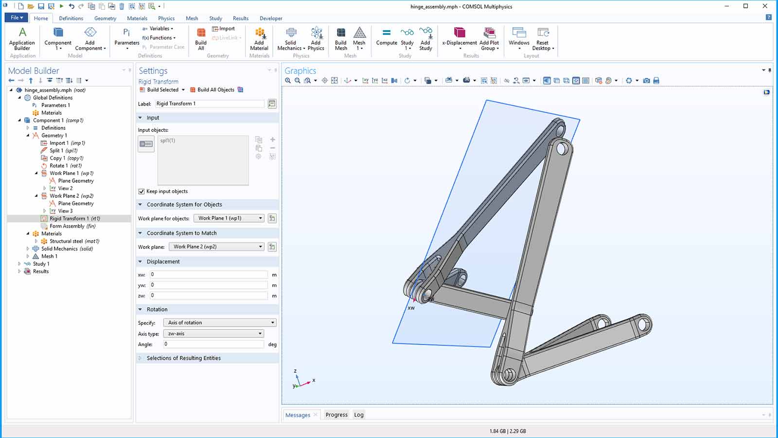 A Rigid Transform feature applied to a hinge assembly model by matching the location and orientation of two Work Planes.
Specify Work Plane by Vertex and Normal Vector
You lot tin now specify a work aeroplane by giving its normal vector and a point or vertex in the plane. Together with the Rigid Transform characteristic, this makes information technology possible to orient an object so that one of its planar faces gets a prescribed normal vector.
New Stop Condition for Interpolation Curve
In the Interpolation Bend feature, you can now choose to use no end condition instead of a given tangent direction or zero curvature. The shape of the bend changes slightly for the open up curve case due to a new underlying curve parameterization scheme.
New Geometry Parts in the Role Library
The Role Library for COMSOL Multiphysics® has been extended to include the five platonic solids (cube, tetrahedron, octahedron, dodecahedron, and icosahedron), as well as a propeller with constant pitch and a random flat surface.
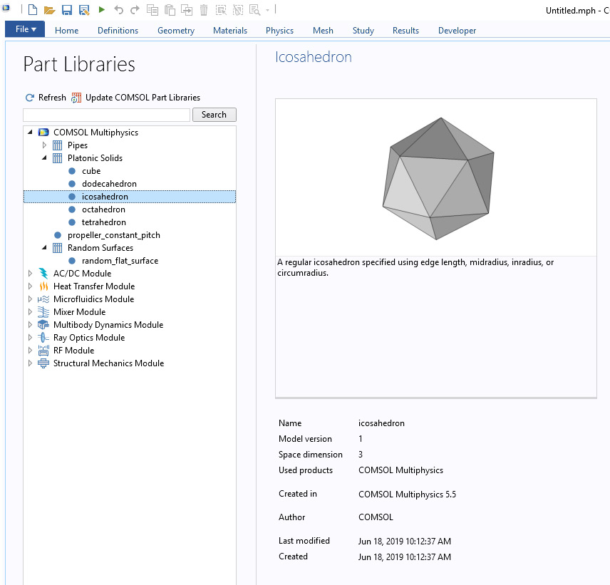 The new icosahedron function instance in the COMSOL Multiphysics® Role Library.
 The new random flat surface function in the COMSOL Multiphysics® Part Library.
Automated Removal of Narrow Face up Regions
The Remove Details functioning has expanded functionality to automatically remove narrow confront regions from your geometry. Past making sure that the Narrow face regions check box is selected (it is selected by default), located in the Details to Remove section, the operation will detect and remove whatsoever narrow face region from your geometry automatically. Y'all can encounter this new feature in the Fluid-Structure Interaction in Aluminum Extrusion model.
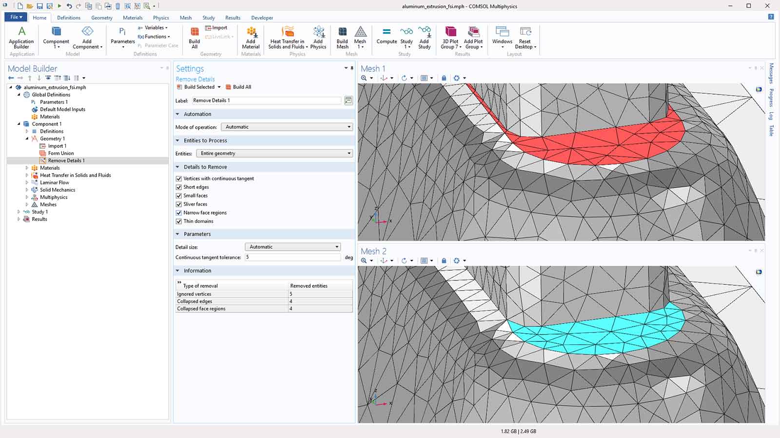 Select the Narrow face regions cheque box in the Details to Remove section to notice and remove them from your geometry. Shown are a confront with narrow regions inducing additional mesh refinement and bad element quality (crimson) and the resulting face later automated removal of the narrow regions (cyan).
Source: https://www.comsol.fr/release/5.5/geometry
Belum ada Komentar untuk "Draw Hinges on a Circle Creo"
Posting Komentar